By Mustafa Pinarbasi
 Cu(In,Ga)Se2 (CIGS) is an excellent absorber material for thin-film solar cells due to its direct bandgap, high absorption coefficient, and ability to yield good quality devices. CIGS-based solar cells have yielded the highest conversion efficiencies of all thin-film solar cells, reaching up to about 20%1). Although successful in yielding small area, high-efficiency laboratory cells, co-evaporation techniques are costly and difficult to scale up. The material utilization rates of such processes are also low. Two-stage processing for CIGS synthesis, in which the CIGS layer is formed through two process steps, offers a lower cost structure and easier manufacturability. In the first step of this technique, a precursor layer comprising Cu, In, Ga and possibly Se is deposited on a substrate at room temperature. In the second step, the precursor layer is treated in a high temperature process environment, typically at atmospheric pressure, to convert the precursor into device quality CIGS film. Although various techniques such as evaporation and sputtering have been employed to prepare precursor layers, electrodeposition offers several advantages. Electrodeposition is a versatile deposition method with ability to yield thin films of metals, metal alloys and compounds which may be used in a wide variety of precursor layer structures. In addition, electrodeposition equipment is low cost and energy efficient since it is typically carried out at low temperatures. Moreover, materials utilization in electrodeposition processes can be close to 100% if stable electrolytes with long lifetime are employed. Electrodeposition is also suitable for high throughput roll to roll manufacturing. Cu(In,Ga)Se2 (CIGS) is an excellent absorber material for thin-film solar cells due to its direct bandgap, high absorption coefficient, and ability to yield good quality devices. CIGS-based solar cells have yielded the highest conversion efficiencies of all thin-film solar cells, reaching up to about 20%1). Although successful in yielding small area, high-efficiency laboratory cells, co-evaporation techniques are costly and difficult to scale up. The material utilization rates of such processes are also low. Two-stage processing for CIGS synthesis, in which the CIGS layer is formed through two process steps, offers a lower cost structure and easier manufacturability. In the first step of this technique, a precursor layer comprising Cu, In, Ga and possibly Se is deposited on a substrate at room temperature. In the second step, the precursor layer is treated in a high temperature process environment, typically at atmospheric pressure, to convert the precursor into device quality CIGS film. Although various techniques such as evaporation and sputtering have been employed to prepare precursor layers, electrodeposition offers several advantages. Electrodeposition is a versatile deposition method with ability to yield thin films of metals, metal alloys and compounds which may be used in a wide variety of precursor layer structures. In addition, electrodeposition equipment is low cost and energy efficient since it is typically carried out at low temperatures. Moreover, materials utilization in electrodeposition processes can be close to 100% if stable electrolytes with long lifetime are employed. Electrodeposition is also suitable for high throughput roll to roll manufacturing.
A wide range of processing approaches employing electrodeposition has been explored for CIGS film formation during the last two decades2)-8). Reader is referred to Lincot et al.2) for a more detailed review of these various electrodeposition approaches.
In one of the previous publications, we described the electrolytes and methods for the electrodeposition of In-Se and Ga-Se films3), which can be used for the preparation of Ga containing precursors and CIGS layers. Using SoloPower’s patented electroplating process, cell efficiencies close to 13.8% on 0.5 cm2 and over 12.2% on 100cm2 were previously demonstrated on flexible stainless steel substrates4,5). In this article, summary of the recent results for roll to roll processing of CIGS absorber will be given and performance of the flexible modules will be presented.
Experimental
Roll to roll Processing
CIGS layers are formed on 50μm thick flexible stainless steel foil. The width of the foil substrates is 0.34 meters and can be up to 500 meter long. After cleaning, rolls are coated with a Mo-based contact layer using a roll-to-roll sputtering tool. The rolls are then transferred to the electrodeposition station where a Cu-In-Ga-Se precursor film containing the preselected composition is electrodeposited on the contact layer in a roll-to-roll electroplating machine. The precursor layers are then subjected to an RTP-type annealing/crystallization process step which converts them into device-quality CIGS layers. The typical temperature range employed in this process step is 500-550°C, although CIGS film formation could be achieved in a wider temperature range of 450-600°C. The thickness of the CIGS layers is in the range of 1-2 μm. Continuous compositional analysis of the precursor layers is carried out by XRF measurements on the electroplating tool as the deposition takes place. Results are also confirmed by Inductively Coupled Plasma (ICP) analysis after cutting coupons from various regions of the processed rolls and then chemically dissolving these coupons to prepare ICP samples.
Typically, a 100nm thick CdS buffer layer is deposited on the CIGS absorber by the Chemical Bath Deposition (CBD) approach using a roll-to-roll deposition system. An intrinsic-ZnO/conductive-TCO stack is then deposited over the buffer layer using a roll-to-roll sputtering tool. The sheet resistance value of the TCO layer is in the range of 40-60 Ω/□ and the transmission within the visible range of the spectrum is over 90%.
The roll of the solar cell stack obtained after the TCO sputtering step is coated with a large number of silver-based finger patterns using a roll-to-roll screen printing tool, which employs a low temperature ink that can be cured at below 250°C. At the completion of this process step, a roll containing thousands of solar cells is obtained. In our research laboratory, CIGS solar cells are also fabricated in a similar sequence using batch processing tools. The cell area for the research studies is about 12 cm2 to ensure that processes developed in the lab can easily be transferred to roll to roll production tooling.
Cell and Module Fabrication and Testing
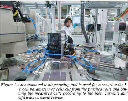
Grid patterns deposited on the roll of solar cell structure define the shape and the size of the devices that are later cut from the roll. An automated roll-to-roll cutter cuts the cells from the rolls based on the pre-selected size of the devices. Cut cells are sorted and binned according to their current and efficiency values using an automated testing/sorting tool (Figure 1). Sorted and binned flexible cells are then interconnected using standard copper ribbons to form cell strings. The stringing method uses conductive adhesives which are cured at temperatures below 250°C. Modules with glass front-sheets and flexible front-sheets are fabricated in a standard vacuum lamination machine. The back sheet is a flexible polymeric foil. I-V characteristics of the cells and modules were measured at SoloPower and selected ones were verified at NREL under standard test conditions (25°C, AM1.5, and 1000W/m2 irradiance).
Results and Discussions
CIGS Processing
One of the most critical aspects of the CIGS formation is composition control. Detailed results on the electroplated CIGS composition control and its impact on the cell efficiencies were discussed previously12). The robustness of the cell properties against small composition variations enhances the manufacturability of the deposition technique. As an example of this flexibility, the electrical performance of cells produced from three different precursor electro-plating recipes is presented in Figure 2. Here the roll-to-roll plating current vs. distance for the Copper, Indium and Gallium is compared against efficiency, Voc and Jsc over a 110 meter section of a roll. Note that the three distinct plating conditions resulted in significantly different precursor Cu/(In+Ga) and Ga/(In+Ga) ratios. Despite the abrupt changes in composition, the efficiency for conditions I and II are nearly indistinguishable. However, a closer examination of the Voc and Jsc characteristics show that the larger Ga/(In+Ga) increased the bandgap as expected resulting in a shift to higher Voc and lower Jsc. The efficiency did begin to degrade in the lowest Ga/ (In+Ga) ratio. However, this is a far larger shift than would ever be encountered from typical process drift. Therefore, subtle shifts in composition due to processing variations will not degrade the performance for electroplated CIGS with two stage process. Another observation is that the Voc or Jsc of the CIGS material can be controlled by changing the conditions of the electroplating process while efficiency remains constant.


Cell and Module Measurements
Figure 3 shows the illuminated I-V characteristics of a 11.8 cm2 area solar cell fabricated in our research laboratory. The total area efficiency of the device shown in Figure 3 is 13.43%. The Voc, Jsc, and FF values are 0.568 V, 36.19 mA/cm2, and 65.36 %, respectively. This efficiency value corresponds to an active area efficiency of about 14.67%. Improved electroplated precursor preparation and RTP processes are responsible for the improved cell efficiencies. These novel processes are currently being transferred to roll-to-roll production line.
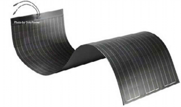
The illuminated I-V characteristics of a SoloPower flexible panel are shown in Figure 4. This panel was 1.5 meters long and produced in the SoloPower manufacturing line. Outdoor performance tests showed similar efficiencies for modules that are 3 meters long. Using low weight front sheet material brings the total weight of the flexible modules to ~2.6 kg/m2. In an earlier publication, we demonstrated rigid modules fabricated in our roll-to-roll line achieved 10% efficiency level12). Improvement of efficiencies from 10% (rigid) to 11.2% (flexible) shows the improvements in our cell processing in less than a year. The material set used to produce the flexible panels were similar to the material set used for rigid panel with the key difference being the replacement of the front glass with a flexible front sheet.

Rigid Panels
SoloPower’s rigid modules have been certified against UL1703, IEC61646, and IEC61730 industry specifications for photovoltaic products. UL and IEC certification for rigid panels were completed in June and August of 2009 respectively. Rigid product (Figure 5) arrays tested in an outdoor test facility at SoloPower since 2009 show robust reliability, with no power loss over a year of operation.
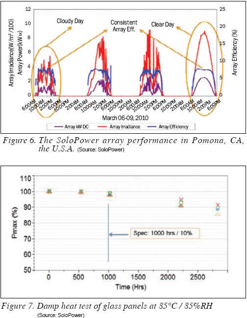
SoloPower modules have also been installed in various external locations to determine their performance. Figure 6 shows the array performance for a period of 4 days with varying light intensities. The data shows that independent of the light level (clear or cloudy day), the panel efficiency is fairly constant.
Solopower’s rigid ‘SP-1’ panels have been tested for an extended period of time, up to 2,800 hours under damp heat conditions. Figure 7 shows the power loss to be around 10% after nearly 2,800 hours of damp heat exposure. These data show that components used in SoloPower products are robust in adverse conditions. Temperature Cycle testing, done at -40°C /90°C for 200 cycles, is required for UL and IEC certification. The rigid panels (SP-1) have been tested for an extended period of time, up to 500 cycles. Power loss in these panels is again around 10% after about 500 cycles of testing, confirming the high quality of components used (Figure 8).

Flexible and Low Weight Panels
SoloPower’s flexible panels share most of the components used for the rigid modules such as cells, back sheet, encapsulation, ribbon, interconnect, adhesives, edge seals, and lamination process. The key difference is that the flexible front sheet with moisture barrier replaces the glass front sheet. One of these flexible modules (approximately 1x3m) is shown in Figure 9.
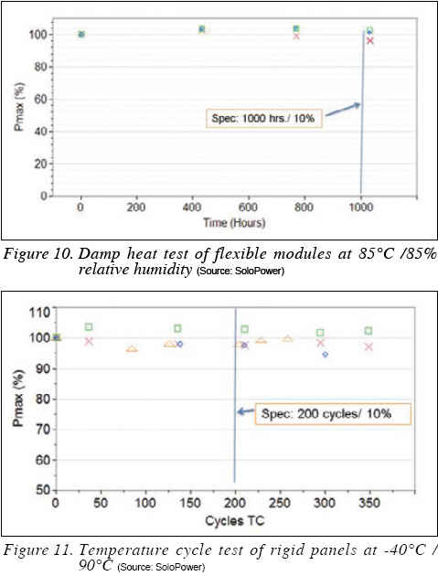
Damp heat is one of the most critical tests for any flexible module as the flexible front sheet barrier must provide protection against moisture over the life of the product. We have tested several modules from the manufacturing line. Damp heat tests conducted on these flexible panels (SFX1-i) showed no power loss after 1000 hours as shown in Figure 10. This is similar to the data that we have observed for rigid modules after 1,000 hours of damp heat exposure.
Flexible panels were also subjected to temperature cycle testing (-40°C /90°C). Results shown in Figure 11 demonstrate that very small or no power degradation is observed after 350 cycles.
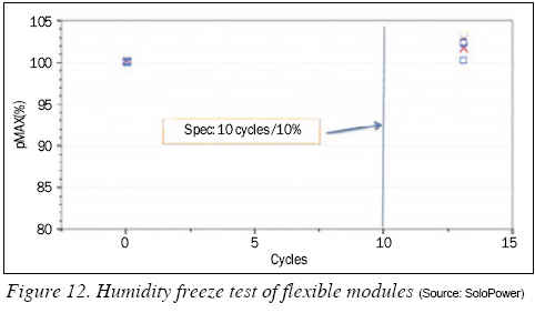
Another critical UL test is the Humidity Freeze Test, where modules are subjected to 85% relative humidity and temperature cycle of -40°C to 85°C alternately. As shown in Figure 12, SoloPower flexible modules show no power degradation after 10 humidity freeze cycles.
Although these tests may not directly correlate to outdoor performance they nonetheless reveal critical information about the robustness of the components and production processes used.
A summary of the results for the electrodeposited CIGS on flexible metal foils at SoloPower was given and performance aspects of the rigid and flexible modules were presented. The electrodeposition process has the capability to control the Cu/(In+Ga) and Ga/(In+Ga) metal ratios reliably. CIGS layers are formed through RTP of the electrodeposited precursors. Solar cells are fabricated in a roll and then cut and sorted for module manufacturing. Both glass and flexible panels were made from interconnection of the cut cells. Flexible panels with aperture efficiency of 11.2% have been demonstrated. Detailed studies show that these panels perform well and retain their Pmax after every standard UL or IEC certification tests including the 1,000 hour damp heat test.
Mustafa Pinarbasi, Ph.D., is Senior VP and CTO at SoloPower (www. solopower.com). Dr. Mustafa Pinarbasi has over 25 years of experience in thin-film materials and processing. Prior to joining SoloPower, he has worked at Hitachi GST and IBM and led the development of many thin-film material and processing technologies for magnetic head devices. Dr. Pinarbasi has authored many articles and holds 165 U.S. patents. He holds a Ph.D. degree from University of Illinois at Urbana-Champaign where he studied amorphous silicon thin films for solar cell applications.
REFERENCES
1) I. Repins, M. A. Contreras, B. Egaas, C. DeHart, J. Scharf, C. L. Perkins, B. To and R. Noufi “19.9% efficient ZnO/CdS/CIGS solar cell with 81.2% fill factor“, Prog. Photovolt: Res. Appl. 16, 2008, pp. 235-239.
2) V.K. Kapur, B.M. Basol and E.S. Tseng, “Low cost methods for the production of semiconductor films for CIS/CdS solar cells‘“ Sol.Cells 21, 1987, pp. 65-72.
3) H.P. Fritz and P. Chatziagorastou, “A new electrochemical method for selenization of stacked CuIn layers and preparation of CIS by thermal annealing“ Thin Solid Films 247, 1994, pp. 129-133.
4) J. Zank, M. Mehilin and H.P. Fritz, “Electrochemical co-deposition of indium and gallium for chalcopyrite solar cells”, Thin Solid Films 286, 1996, pp. 259-263.
5) R. Friedfeld, R.P. Raffaelle and J.G. Mantovani, “Electrodeposition of CIGS thin films”, Sol. Energ. Mat. Sol. C. 31, 1999, pp. 163-167.
6) M. Ganchev, J. Kois, M. Kaelin, S. Bereznev, E. Tzvetkova, O. Volobujeva, N. Stratieva and A. Tiwari, “Preparation of CIGS layers by selenization of electrodeposited Cu-In-Ga precursors”, Thin Solid Films 511-512, 2006, pp. 325-327.
7) A. Fernandez, M. Calixto, P. Sebastian, S. Gamboa, A. Hermann and R. Noufi, “Electrodeposited and selenized CIS thin films for photovoltaic applications”, Sol. Energ. Mat. Sol. C., 52, 1998, pp. 423-427.
8) R. N. Bhattacharya, W. Batchelor, J. E. Granata, F. Hasoon, H. Wiesner, K. Ramanathan, J.Keane, and R. N. Noufi, Sol. Energ. Mat. Sol. C., 55, 1998, pp. 83-87.
9) D. Lincot, J.F. Guillemoles, S. Taunier, D. Guimard, J. Sicx-Kurdi, A. Chaumont, O. Roussel, O. Ramdani, C. Hubert, J.P. Fauvarque, N. Bodereau, L. Parissi, P. Panheleux, P. Fanouillere, N. Naghavi, P.P. Grand, M. Benfarah, P. Mogensen, O. Kerrec, Sol. Energy, 77, 2004, pp. 725-729.
10) S. Aksu, J. Wang and B. Basol, “Electrodeposition of In-Se and Ga-Se thin films for preparation of CIGS solar cells“, Electrochem. and Solid-State Lett. 12, 2009, pp. D33-D35.
11) B. Basol, M. Pinarbasi, S. Aksu, J. Wang, Y. Matus, T. Johnson, Y. Han, M. Narasimhan, and B. Metin, “Electroplating based CIGS technology for Roll-to-Roll Manufacturing”, Twenty third European PVSEC, 2008, pp. 2137-2141.
12) B. Basol, M. Pinarbasi, S. Aksu, J. Freitag, P. Gonzalez, T. Johnson, Y. Matus, B. Metin, M. Narasimhan, D. Nayak, G. Norsworthy, D. Soltz, J. Wang, T. Wang, H. Zolla, “Status of electroplating based CIGS technology development” Thirty fourth IEEE PVSC, 2009, pp. 2310-2315.
For more information, please send your e-mails to pved@infothe.com.
ⓒ2010 www.interpv.net All rights reserved.
|


.jpg)