By Rich Wells, Mark Francis

 Electrically-Conductive Adhesives (ECAs) have been an integral part of the electronics industry for years. An emerging application for ECAs is solar cell interconnects in which the ECA joins the metallization on two adjacent cells. ECAs typically require high percentages of silver-based powders and flakes to provide electrical conductivity. Solder rivals ECA as a reliable interconnect and has the distinct advantage of exhibiting lower cost since high percentages of precious metals such as silver are not used. However, many interconnect applications in the solar industry are precluded from using solder because of the necessary high soldering temperatures and the inherent high stress at the solder-substrate interface.1), 2) In addition to reducing interfacial stress, ECAs can be formulated to be flexible and ‘rubber-like’, enabling highly flexible thin film solar cell designs.3) Electrically-Conductive Adhesives (ECAs) have been an integral part of the electronics industry for years. An emerging application for ECAs is solar cell interconnects in which the ECA joins the metallization on two adjacent cells. ECAs typically require high percentages of silver-based powders and flakes to provide electrical conductivity. Solder rivals ECA as a reliable interconnect and has the distinct advantage of exhibiting lower cost since high percentages of precious metals such as silver are not used. However, many interconnect applications in the solar industry are precluded from using solder because of the necessary high soldering temperatures and the inherent high stress at the solder-substrate interface.1), 2) In addition to reducing interfacial stress, ECAs can be formulated to be flexible and ‘rubber-like’, enabling highly flexible thin film solar cell designs.3)
Because cost reduction is imperative for potential grid parity in the solar industry, ECAs with high levels of silver present a potential barrier for cost reduction. Typically, most ECAs are filled with 75-90% silver to create conductivity in a polymeric matrix. Although the search for silver alternatives has been ongoing for years, the necessity for cost reduction in the industry is driving the fresh search for alternatives. Furthermore, the recent significant escalation in the cost of silver has dampened cost-cutting goals for many in the solar industry.
Along with cost reduction, both mechanical and electrical performance as well as long-term reliability cannot be compromised. With module makers ensuring greater than 20 years of stable performance, the interconnect must survive thermal cycling and high humidity with minimal degradation of electrical and mechanical properties. Therefore, silver alternatives must maintain reliability as well provide cost benefits.
Electrically-Conductive Adhesives
ECAs are liquid monomer materials that polymerize into a thermosetting polymer upon heating. By nature, the polymer network is electrically-insulating with an electrical resistivity in the range of 1 x 10¹⁴ ohm.cm. The ECA is filled with small conductive particles in the range of 5-50 μm. The particles are engineered to provide the best possible contact between the particles. When a certain loading of particles is exceeded, a contiguous conductive network is formed within the polymer network. At this loading, termed the percolation threshold, the conductivity of the ECA makes a significant increase in conductivity and in many cases approaches the conductivity of the conductive particle used. Silver, one of the most popular choices, has a resistivity of 1.6 x 10⁻⁶ ohm.cm. Silver-loaded ECAs characterized by the basic percolation theory can have resistivities as low as 1 x 10⁻⁵ ohm.cm, enabling the polymer matrix to undergo a resistivity change of nearly 20 orders of magnitude.
Generally, the conductivity of the ECA composite can be related to the volume fraction of conductive filler by a simple power relation:
σ = σ0(V-Vc)s
where σ is the conductivity of the composite, σ0 is the conductivity of the conductive filler, V is the volume loading of conductive filler and Vc is the volume loading at the percolation threshold. Intuitively, to reach resistivities approaching the resistance of the conductive particle, relatively high loadings of conductive particles must be used. If the particles are silver, the cost of the ECA composite is impacted.
In addition to high loadings, the particles must intrinsically possess low resistance. To generate low-resistance ECAs, typically one is limited to the highly conductive metals such as gold, silver and copper. Silver has become the most prominent choice because gold is prohibitively expensive and copper will form an electrically-insulating oxide layer on the surface of the particle. Although silver may oxidize slightly, the oxidation layer is, in fact, conductive.
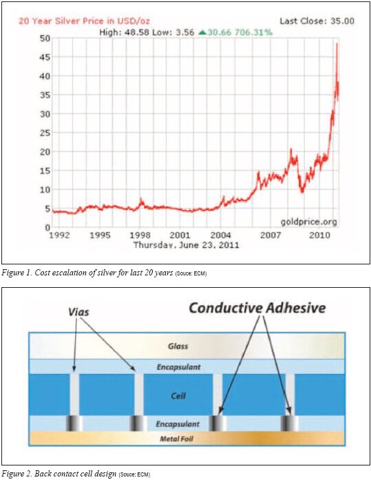
Despite the fact that high loadings of expensive silver particles are required in ECA formulations, the recent escalation of the cost of silver has created additional price strain for those who use ECAs in the solar industry. The price trend for silver over the past 20 years is shown in Figure 1.
.jpg)
The most notable application in the solar industry for ECAs is cell ribbon attach. Traditional c-Si cells have used solder as a means to interconnect silicon cells with a solder-plated copper ribbon. With the advent of thin film PV, the use of temperature-sensitive substrates and PV layers have precluded the use of solders for ribbon attach, making ECA a popular alternative.
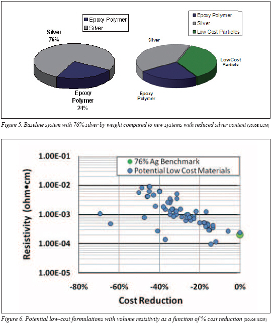
An emerging application for ECAs is in back contact cell designs. With back contact cells, the contacts from the c-Si cell and the contact from the back sheet need a conductive interconnection.4) When ECA is employed as the interconnect, it is typically stenciled to the conductive metallization on the back contact sheet sometimes called a metal foil. Dielectric layers are applied in the proximity of the ECA on the back sheet. The PV cell is applied, and the back contact sheet, ECA and PV cell are laminated to create the contact. Ideally, the ECA can be cured during this lamination step. A depiction of the back contact design is shown in Figure 2.
Reliability Testing: Damp Heat
Accelerated damp heat testing is typically conducted to indicate potential moisture-induced failures that could occur over the life of the solar module. During damp heat conditioning, the high free volume passes relatively high levels of moisture vapor into the bulk of the adhesive that diffuses to the adhesive-metal interface. With water, electrolyte (ionic species typically in the adhesive) and an electrochemical potential difference between the ECA and the substrate, a galvanic cell is formed, enabling the growth of a nonconductive oxide on the non-noble tin surface. The interfacial resistance will increase, resulting in cell performance decay.
Although the solar cell is encapsulated, polymeric materials are unable to provide a complete hermetic seal from moisture permeation. Moisture will diffuse into the cell, and certainly the possibility exists that moisture may not diffuse easily out of the cell. In order to exasperate the effect of moisture, the adhesive and ribbons were exposed to 85˚C/85% humidity (damp heat conditioning) without encapsulation. Essentially, the ribbon-adhesive assembly was exposed directly to the damp heat conditions without any barriers.
A test scheme was developed in which the ribbons were joined with ECA in series creating 12 ribbon-adhesive interfaces. The ribbons were affixed to a sheet of Kapton in the pattern shown in Figure 3, and the adhesive was dispensed and cured. One hour at 150˚C was chosen as the cure condition to ensure complete cure of the ECAs. The resistance was measured using a Keithley 2750 four-point probe multimeter at the points identified in Figure 3. The measurement will take into account the resistance of the ribbons, the six adhesive beads and most importantly, the 12 ribbon-adhesive interfaces.

After an initial resistance value was taken, the test pieces were placed in the damp heat chamber at 85˚C/85% RH conditions. The parts were removed periodically and resistance was tested before returning the samples to the chamber. Testing was performed for 1000 hours. Sanding of the ribbon to remove any oxide was performed where the probes were placed to ensure a good connection to the ribbon. The series connection of several interfaces amplifies any corrosion signal.
Simple Measures First
Because of the cost reduction urgency for the industry, a holistic approach is necessary. Besides ECA cost reduction, other measures can be implemented to contribute to the overall savings. For instance, in a new cell design, the constraints and bottlenecks of the cell series resistance typically require exploration. Empirically, engineers need to determine exactly how much electrical conductivity is required for the ECA. As mentioned, resistivity of the ECA will trend with silver filler loading. If the application is using a highly-filled ECA that is orders of magnitude lower in resistance than other resistive bottlenecks in the cell assembly, then an opportunity exists to relax the conductivity-resistivity requirements of the ECA. As a result, the silver loading of the ECA can be reduced and a cost benefit can be realized. Obviously, in order to harness the benefit of a relaxed conductivity-resistivity, empirical work must be conducted to ensure that sufficient conductivity margin exists in the ECA.
Another intuitively obvious step is to investigate the amount of ECA used on the application. In a ribbon attach application, the width of the bead could be explored as an option to reduce cost as long as sufficient mechanical and electrical properties are maintained. Bond lines also can be reduced. Although a universal bond line recommendation is difficult, a 25 μm bond line is a good rule of thumb.
Enabling the use of cheap metallization is an ancillary benefit of choosing the right ECA. In the back contact design, it is customary to provide a silver metallization on the back contact sheet. The noble metal character of silver provides a high-reliability contact for the ECA-metal interface, often enabling survival through damp heat conditioning. A recent development has allowed module makers to eliminate the silver metallization and rely on lower cost copper back sheet metallization. Figure 4 shows 85/85 damp heat reliability series resistance of daisy-chained ECA-copper joints in which the 1000-hour reliability essentially is unchanged and in these two formulations the resistance actually decreased.
The results represent a truly worst case, accelerated conditioning where the scheme is not encapsulated and is subjected directly to the 85/85 environment, making stable modules performance with low metallization a plausible reality. Novel, proprietary methods were implemented in the pretreatment of the copper to synergize with the components of the ECA chemistry.
Cost Reduction of ECA
Suggestions abound for alternatives to silver for ECA formulations. Simple low-cost metals such as nickel, copper, and tin have been suggested as well as exotic nano materials including silver nanowires and carbon-based nanotubes. Since the majority of conduction across a conductive particle occurs on the surface of the particle, many have resorted to silver coatings on various low-cost materials to reduce the amount of silver. Materials with different core particles and levels of silver coatings have been developed as alternatives to pure silver particles.


As previously suggested, despite the attempts to eliminate silver, the equations suggest that a relatively high level of noble-metal (silver) is required to create the percolation network and transform a nonconductive polymer to a conductive composite. An approach was taken to initiate incremental cost savings by replacing portions of the silver content. Initial goals of 20-40% cost savings could at least provide some cost relief to the end-user. Arbitrarily, an ECA with loadings of 76% by silver was chosen as the benchmark for cost improvement. Many ECAs contain higher loadings of silver either unnecessarily or perhaps the higher loading is dictated by the application. Regardless, the cost of 76% silver-filled epoxy-based material provides a standard for comparison.
An important attribute for ECAs in solar applications is to minimize off-gassing of volatile organic materials during the cure. Off-gassing can result in the formation of voids in the bond line. Many ECAs contain high levels of volatile materials in the formulation and the base cost of an ECA could be reduced significantly by simple dilution with a volatile solvent. Consequently, a solar cell manufacturer is receiving less ECA for the price when dilution occurs. For the purpose of the study and with the end application of minimal volatility in mind, the test formulations do not contain volatile organic materials.
To rival a standard 76% filled system, care was taken to choose a chemistry that would exhibit reliability in the end application. The low-cost alternative composition will need to maintain stable joint resistance during 85/85 damp heat testing. A high-reliability resin chemistry was chosen and the various conductive particles were blended with silver with the goal of reducing the levels of silver in the final composition. Conductive particles with varying aspect ratios, particle sizes and coatings were evaluated and blended with standard silver conductive particles at various volume loadings in the formulations.
The costs of the various blends were calculated and compared to the 76% silver-loaded benchmark system. Because an adhesive application uses a volume of material (the weight is a consequence of the volume applied and density of the adhesive), all cost calculations are the cost per volume and not cost per weight of adhesive. The percent cost reduction of all test formulations relative to the 76% silver system was plotted against the log of the resistivity as shown in Figure 6. It is important to note that the market silver cost of US$30 per troy ounce is used for the initial calculations.
The chart shows a strong trend illustrating that as formulation cost is reduced the consequence of increasing resistivity is realized. Interestingly, there appears to be opportunity to reduce cost by nearly 20% without major sacrifice in volume resistivity. However, substantial improvement beyond 20% cost reduction results in increasing resistivity values.
Two blends of interest are shown in Figure 7. Blend #1 is a conductive particle that when blended at various ratios and loading of silver results in significant cost savings with a somewhat linear loss in resistivity with cost savings. Most notably, with increasing loadings of the alternative conductive particle, the viscosity of the system was essentially unchanged, allowing significant loading of the alternative conductive particle. On the contrary, the conductive particle used in Blend #2 maintained a low resistivity for cost reductions up to 40%. However, with only small introductions of the particle, the viscosity of the system became unworkable and could not be applied in a typical application.


The market price of US$30 per troy ounce was chosen arbitrarily, but certainly as the market price of silver fluctuates, investigation of the cost savings is of interest. Higher market silver costs will result in a much larger magnitude of cost savings with alternative conductive particles. In Figure 8, the percent cost savings is shown for blend #1 at US$30 and US$40 market price for silver. The percentage of cost savings is only marginally better with an increase in market silver cost. Since the percentage of cost savings is relatively the same, the user will realize substantial cost savings even if the market price of silver plummets.
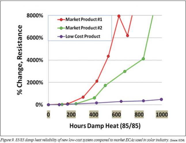
One system with a low-cost blend was subjected to damp heat series resistance testing on tin-silver ribbons. In Figure 9, the ECA with the low-cost blend is shown compared to two market ECAs that pass damp heat reliability in solar module reliability testing. Despite the slight increase in series resistance in the low-cost product, it is orders of magnitude better than products that successfully pass damp heat reliability testing in a finished, encapsulated module. The series resistance testing without encapsulation simulates a very aggressive and unlikely condition in the field where other materials in the module are likely to fail first.
For the development of the solar industry, reliable conductive interconnects are essential. ECAs provide a reliable solution for many interconnect designs, but the escalation of silver cost has created cost hurdles for the industry. Replacing portions of silver particles in the ECA with other lower cost conductive particles provides an avenue for cost reduction independent of the market price of silver.
Careful attention to the design of applications also provides options for cost reduction. It is important to determine the amount of ECA used for the application. Excessive bond line thickness should be avoided.
For back contact cell designs, novel chemistries enable the use of lower cost copper substrates in place of more expensive metallization. Furthermore, expensive in-line ovens can be removed and the ECA can be cured during the lamination process.
Rich Wells received his B.A. in Chemistry at Anderson University and earned a M.S. in Polymer Science from the University of Akron and is the Chief Technical Officer at Engineered Conductive Materials, LLC. (www.emsadhesives.com)
Mark Francis received his B.S. in Chemical Engineering from the University of Massachusetts, Lowell and is the Global Business Manager, Solar at Engineered Conductive Materials, LLC.
REFERENCES
1) B.R. Olaisen, M. Edoff, A. Holt, 24th European Photovoltaic Solar Energy Conference, 21-25 September (2009) 3007-3010.
2) H. Wang, Y. Zhang, X.L. Kou, Q. He, Y. Sun, 24th European Photovoltaic Solar Energy Conference, 21-25 September (2009) 2961-2963.
3) R. Wells, M. Francis, PV Production Forum 2010, Global Solar Technology January (2011) 16-20.
4) T. Adcock, A. Henckens, Photovoltaics World, May/June (2011) 25-28.
For more information, please send your e-mails to pved@infothe.com.
ⓒ2011 www.interpv.net All rights reserved.
|


