By Marty Burkhart, Hanspeter Mueller, Markus Reutz
 Once upon a time drinking water was conveyed in hollowed-out tree trunks1). As late as 1934, large diameter wooden staved pipes of redwood and Douglas fir could still be seen carrying water through the hillsides to remote populated areas in the United States2). At the same time, choices for connections to homes wandered from lead pipes to galvanized iron to copper and even some plastics. It is surprising to note that as recent as 2007 Providence Water in Rhode Island reported that some 23,000 of its connections were still using pipes made of lead3). A similar evolution, but on a faster pace, can be presented in the conveyance of water used in the high-tech industries; be they the production of microchips, flat panel displays, photovoltaic cells, LEDs, biotech or pharmaceutical applications. The biotech industry, for example, recognized that metals, a life science material of choice, within their high purity water would shutdown vital enzymatic synthesis processes4). And, early wafer fabs still used stainless steel to convey some process waters up until the late 1980s5). That is to say, once upon a time piping system materials that are undesirable today dominated early high-tech production installations. Nevertheless, even with our sophisticated knowledge on materials of choice for pure water piping systems, there remains confusion on the proper positioning of these materials. Therefore, the authors intend to clear up some of the confusion and suggest some niches for each. The authors are not presuming to say that lesser grades of materials can’t be used for high-tech pure water applications. Rather, that the proper initial selection will provide a longer lasting, more palatable service. After all, hollowed-out tree trunks served our ancestors for centuries.
Sample Preparation
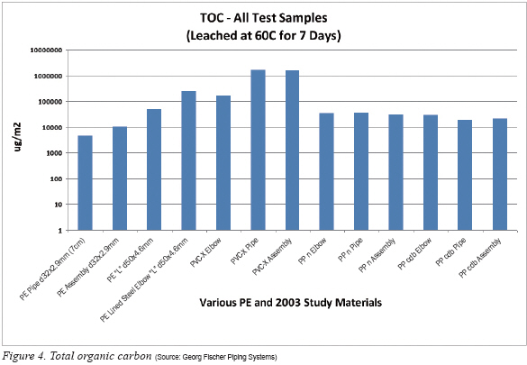
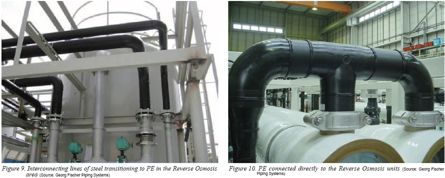
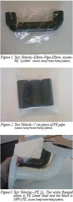 Samples of 32 mm and 50 mm outside diameter PE pipes and fittings were obtained through normal distribution channels and in their original factory packaging. The elbows were used to make assemblies (see Figure 1). For the pipe test, the samples were cut to lengths of 7 cm each and repackaged (see Figure 2). The pipe cutter used was thoroughly cleaned with isopropyl alcohol before use and the pipe samples were washed with Ultrapure Water (UPW). In addition, some pipe pieces were cut to make assemblies with the elbows in two variations and using the manufacturer’s preferred method of joining. The first configuration were 32 mm elbow-pipe-elbow assembly pieces constructed under clean conditions, according to good installation practice and intended to simulate a ‘piping system’ (see again Figure 1). The second variation was a 50 mm 100% PE elbow welded to a 50 mm piece of 100% PE pipe in an L shape, to be compared directly with the leachout results of a concomitantly tested PE Lined Steel Elbow (see Figure 3) where the outer white shell is painted steel and the inner liner is 100% PE. These two pieces will occasionally be referred to in the remainder of this document as Ls. All test pieces were bagged into special high purity PA/PE packing foils after preparation and delivered to the Analytik fuer Technik und Umwelt.
At the ATU, the preparation was carried out in Class 1 clean benches, located in Class 1000 cleanrooms, in accordance with SEMI F407) and SEMI F578), using cleaned containers that meet the SEMI criteria. All metal impurity levels in the UPW used for pre-washing, making of standards and blanks as well as the UPW eluant itself were measured below 1 to 5 ppt (parts per trillion). The conductivity was 18.2 MΩ-cm and the Total Organic Carbon (TOC) level was at 2 ppb. Nitric acid of ULSI quality was used to stabilize the metals within the UPW eluant. The ends of each assembly as well as the Ls were sealed with a clean method. The 7 cm pipe pieces were removed from their packaging in a cleanroom, pre-washed 10x with UPW and placed into UPW as is. The elbow-pipe-elbow assemblies and Ls were also removed from their packaging in a cleanroom and pre-washed by filling and dumping 10x with UPW. The UPW from the eleventh fill remained in the elbow-pipe-elbow assemblies and Ls. The test items were capped and placed in an oven along with the PFA vessels containing the pipe pieces. All test items were statically leached for a period of 7 days as outlined in SEMI F40 and SEMI F57. Due to the service temperature of the PVC-X examined in the 2003 study, a temperature of 60°C was selected to match with those results instead of the SEMI F57 required 85°C. The reasons for using SEMI static test methods and such high temperature testing when the actual usage of the material might be much lower is detailed within the 2003 study. However, in short, these static and accelerated tests speed the leaching process that will eventually happen over time. And, testing statically removes the possible contamination hazard brought in by extraneous equipment needed for dynamic testing. To carry out the static leaching the top opening of elbow-pipe-elbow assemblies and Ls were fitted with a convenient way to decant the UPW once the leachout was complete. This was accomplished by using a pre-cleaned PE film with the leached sample-ends upturned so the soaking solution would not come into contact with the PE film. A set of 5 blanks was prepared (in the vessel type of use for that particular test) to determine the detection limits and the preparation procedure as described in some detail in the 2003 study.
After leaching, the metallic contamination was analyzed using an Agilent 7500 cs quadrupole ICP-MS. External calibration used NIST reference and traceable standards. All blank, standard and sample solutions were in the same matrix. TOC was analyzed with thin-film UV-oxidation, using NIST reference and traceable standards for calibration. Of interest was the ‘Non Purgable’ Content (NPOC). The detection limits for the elements are defined as three times the standard deviation of the blank solutions using a 3-sigma method. Blank values were subtracted from the sample results and the concentrations were calculated as micrograms of contaminant per square meter based on the total volume of solution and component surface area.
Results and Discussion
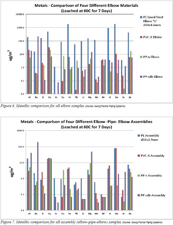
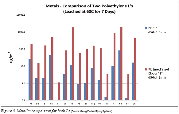
Prologue: Important to the reader is that only the PE results are new to this study. The authors borrowed the Polyvinyl Chloride Clean (referred to as PVC-X), Polypropylene Natural (referred to as PPn) and Polypropylene Cleaned and Double Bagged (referred to as PP cdb) values from the aforementioned 2003 study to make one-on-one comparisons without repeating the testing. All conditions were the same in terms of material selection, handling, sample prep and testing. Therefore, similar results, that is to say, within the inherent variation of raw materials and manufacturing processes, should be achievable. Focusing on Figures 4 through 8 the PE TOC and metal leachout results can be compared to the 2003 study for the various pipes, elbows and elbow-pipe-elbow assemblies. Unlike the 2003 study, no separate PE elbows were tested. Therefore, Figure 6 uses the popular lined steel elbow shown in Figure 3 as a comparison means.
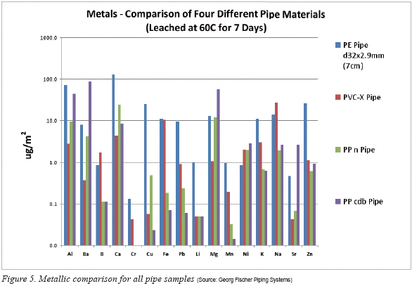
Total Organic Carbon: Figure 4 is set to a logarithmic scale so that all materials can be plotted together. As was pointed out in the 2003 study, the PVC-X pipe and assembly (elbow-pipe-elbow) have the greatest amount of TOC leachout. In both of these cases these test vehicles are acting as a ‘system’ where glue, rich in TOC, must be used to join the endcaps for the pipe or the elbows to pipe in the assembly configuration. The 2003 study discusses in detail the characteristics of the glue needed to join the PVC-X; all PE, PPn and PP cbd samples were joined using IR Plus® techniques that use a non-contact heat fusion process.
In the case of the PVC-X elbow borrowed from the 2003 study, the TOC is less, helping to confirm that glue adds at least an order of magnitude to the contamination. Still the results from the PVC-X elbow is not near what would be considered adequate for the requirements found in SEMI F57, that being 60,000 ug/m2 maximum at 85 C. Surprisingly though is that the PE Lined Steel Elbow (see again Figure 3, white flanged elbow) leached a TOC value between that of the virgin PVC-X elbow and the glued PVC-X pipe. The source of this excessive TOC is not readily known but it can be speculated that residual oils in the making of the steel outer shell might have somehow migrated to the flow path area of the inner PE liner. In either the case of PVC-X glue or the PE Lined Steel Elbow, TOC can act as foodstuff for bacteria and the subsequent growth of biofilms9) that become dangerous particles within the water system.
Turning attention to the PPn and PP cdb TOC results it is noted that these fall within the limits of SEMI F57, as do the PE samples which are a little better for the PE pipe and assembly. However, the reader should be cautioned once again that these results contain two caveats. First, the leachout was at 60°C and not the required 85°C. Second, this is a snapshot and not an extended study comprised of several leachout trials. It is well known that formulas for PE and PP vary widely from the same manufacturer and neither material was ever intended for high purity applications like required in SEMI F57.
Metals
In the case of displaying the metals leached, once again the y-axis scale is set to logarithmic. Figure 5 groups all the pipes together; Figure 6, the elbows; Figure 7, the elbow-pipe-elbow assemblies; and finally Figure 8, the Ls. A detailed discussion of the metallic leachout comparison for PPn, PP cdb and PVC-X is found in the 2003 study. Therefore, the following discussion will focus only on the PE portion of the results as they pertain to the other materials. Drawing the reader’s attention to the pipe results (Figure 5), the major contributors to the contamination are calcium, aluminum, copper, zinc, barium and lead, leaching one to two orders of magnitude greater than the other materials. This is not surprising since the monomer for PE is derived from a naturally occurring gas in the earth’s crust (ethane) and without costly purification the contaminates will vary widely from batch to batch. All other metals detected were comparable to the other materials tested and several challenged the analytical equipment used for detection.
Switching to the elbows (Figure 6) it stands to reason that iron is the major culprit in the PE Lined Steel Elbow. Not far behind were sodium, potassium and again, calcium. Following that was barium, magnesium, manganese and again, lead. Of very curious interest is the high lithium value in the PE Lined Steel Elbow. This is unusual since we have not seen it before in such a high amount when performing static leachout of polymer materials. The source is unknown but it is common knowledge that lithium stearate, for example, is used as a high temperature grease. If a carbon rich ester like stearate were present it could also be a contributor to the high TOC seen in Figure 4.
The PE assemblies seen in Figure 7 showed much cleaner results for metallic leachout. In only a few cases were the results higher than those from the materials researched in the 2003 study.
The last comment about the leachout testing is the comparison of PE Lined Steel Elbow verses 100% PE as seen in Figure 8. Since the lined steel elbow values are the same from those of Figure 6, the discussion is essentially the same for the findings. However, noteworthy is that there was not a single element where the lined steel elbow was better than the 100% PE elbow. In fact, in all cases the lined steel elbow was one to two orders of magnitude greater in contamination across the board.
Unrelated to the leachout testing that we performed are two separate independent studies by Georg Fischer Piping Systems. One is yet to be published10) and the other was presented during 2010 at the Plastic Piping Conference XV11). Concerning the former unpublished work, towards the end of 2008 a key customer in Japan became interested in looking at materials other than PVC and PVDF. Early the next year a study was launched to evaluate PE. At the same time, the customer had been using PE lined steel for many applications before but was not sure about the mechanical behavior of the material. Their concerns were driven by knowledge of PVC and even a specially developed PVC HI (high impact) and how these responded to water hammer, vibration and other mechanical issues. An all inclusive polymer study took place and showed that piping systems out of thermoplastic materials like PE, PP and PVDF show a quite forgiving behavior under cycling loads or hydraulic shocks (water hammer). The level of E-Modulus can indicate the ability to absorb cycling loads. A low E-Modulus means that the material can compensate cycling loads or hydraulic shocks (water hammer) by deformation and of course the E-Modulus of thermoplastics is much lower than the metal counterparts. In fact the peak stress level for steel pipes with water hammer (Joukowsky12) shock) is at least 3 to 5-times higher compared to common thermoplastic pipes.
In the presented work11), the general theme shows that PE has a place in industrial piping system installations and should not just be relegated to underground water and gas utilities consisting of straight runs. With the advent of IR Plus® welding complex pipe runs, as often found in industry, are not only possible but encouraged by the findings within the reference.
Summary and Conclusions
True high purity materials require:
-Special production, handling and packaging of raw polymer materials provided by polymer suppliers with the intent of being later produced into high purity pipes, fittings and valves.
-Special incoming inspection and handling of the raw polymer material at the piping system manufacturer’s site.
-Special production techniques including cleanroom production and clean handling at the piping system manufacturer’s site.
?Special and specified packaging materials for the finished products that will withstand delivery and not contaminate the product.
However, not all customers’ applications really need true high purity piping system components. Clean systems, that is to say, standard products with cleaned surfaces will suffice in a number of cases. And, some areas of the make-up water, before reverse osmosis or polishing for example, can be common materials of construction, or even feed the entire piping system within an ordinary factory that does not need the highest quality. So-called High Purity Polypropylene, Clean Polyvinyl Chloride and oil-free products are obviously not HP systems. But these are (surfaced) cleaned systems and after a certain time period of a few months the leach-out data can reach an acceptable level for a wide range of applications. The use and market share of Clean Systems is also regionally different, but especially in Asia widely accept for all, except the most critical applications13).
However, the fact is that there are few polymer materials truly recognized as transporting high purity fluids and being called ‘High Purity’. Those are Polyvinylidene fluoride (PVDF), recognized by ASTM D5127-0714), Perfluoroalkoxy (PFA) and Polytetrafluoro-ethylene (PTFE). Materials like polyvinyl chloride, polypropylene and polyethylene do not meet the requirements of ‘true’ high purity as outlined above. Slowly high tech manufacturers are beginning to learn this and one leading Asian chip manufacturer who has been a loyal Clean Polyvinyl Chloride user for years admitted that it would not work for 22 nm and a likely switch to PVDF would be needed15).
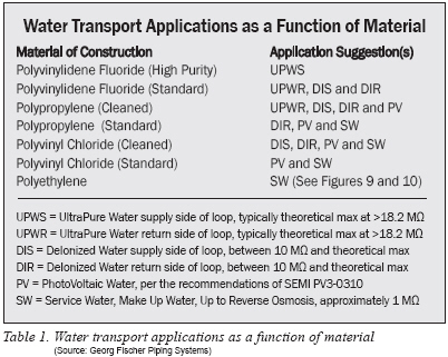
Nevertheless, polyvinyl chloride, polypropylene and polyethylene do have their place in the high-tech industries. One such example is found in photovoltaics16) where these materials are common. And, based on the leachout results presented in this study PE does have a place within water systems, as seen in Figures 9 and 10.
Last, Table 1 suggests some application niches for the various materials.
Marty Burkhart is High Purity Consultant and Hanspeter Mueller is Microelectronics Segment Manager Dipl.Ing. Mechanical Engineering (TH) at Georg Fischer Piping Systems (www.piping.georgfischer.com).
Markus Reutz is Trace Analysis Manager Dipl.-Ing. Chem.(FH).
REFERENCES
1) “Discussion” by Harry G. Payrow, “Historic Review of the Development of Sanitary Engineering in the United States During the Past One Hundred and Fifty Years: A Symposium,” Transactions of the American Society of Civil Engineers, Volume 92 (1928), p. 1287.
2) H. K. Barrows, Water Power Engineering, Second Edition (New York and London: McGraw-Hill Book Company, 1934), pp. 376-385
3) Providence Water, Press Release May 24 2007
4) Petrossian A, Smart N and Proietto RP,” Designing a Flexible Facility for Biopharmaceuticals”, BioPharm, Vol. 6, 1993, pp 40-45
5) Personal observation by one of the authors, a 1 micron fab located in Dallas, TX, 1989.
6) Burkhart M, Bittner M, Williamson C and Ulrich A, “A Scientific Look at Lab Quality Deionized Water Piping Materials,” Ultrapure Water, November 2003, pp. 36 - 43
7) SEMI F40-0699,”Practice for Preparing Liquid Chemical Distribution Components for Chemical Testing”, Semiconductor Equipment and Materials, 3081 Zanker, San Jose, CA 95134, USA
8) SEMI F057-00-0301, “Provisional Specification for Polymer Components used in Ultrapure Water and Liquid Chemical Distribution Systems”, Semiconductor Equipment and Materials, 3081 Zanker, San Jose, CA 95134, USA
9) Mittleman MW and Geesey GG, “Biological Fouling of Industrial Water Systems: A Problem Solving Approach,” Water Micro Associates, 1987, pp. 203-208
10) Loeffler M, Brueggenmann- Mortier K and Werner U, “Special Report on a Series of Pulsation Pressure Tests at LAB with different Materials” (Working Title), August 2010
11) Sixsmisth T, Wermelinger J, Williamson C and Burkhart M, “Advantages of Infra-Red Welding of Polyethylene Pipes for Industrial Applications”, presented at the Plastic Pipes Conference XV, Vancouver, Canada, September 20-22, 2010
12) Kay M, “Practical Hydraulics,” (2nd ed.) Taylor & Francis, 2008, p. 20
13) Private communication with Peter Walder, September 2010.
14) ASTM D5127 Standard Guide for Ultra-Pure Water Used in the Electronics and Semiconductor Industries
15) Private conversation with Casey Williamson, Semtec Inc., June 2010.
16) SEMI PV3-0310, Guide for High Purity Water used in Photovoltaic Cell Processing

For more information, please send your e-mails to pved@infothe.com.
ⓒ2011 www.interpv.net All rights reserved.


.jpg)