A willingness to install east-west orientated Photovoltaic (PV) systems has lacked in the past. Nowadays, however, interest in installing PV systems on east-west roofs is steadily increasing. Although south-orientated systems are better, east-west orientated PV systems can also generate substantial earnings. Moreover, due to the sharp drop in module prices, increased demand for east-west systems are expected for the future. From the perspective of grid operators, east-west orientated PV systems are preferable to south-orientated ones, as the energy is fed-in more evenly throughout the day, therefore reducing power peaks thus relieving the grid. Up to now it was assumed that east-west orientated PV systems require separate inverters for each orientation, or at least one inverter with multiple MPP (Maximum Power Point) trackers, to avoid mismatching losses. This article will show an analysis of east-west orientated PV systems connected to one MPP tracker and demonstrate the high performance of such systems.
By Dipl.-Ing.(FH) Dietmar Staudacher

.jpg) Based on theoretical analysis, the behavior of the MPP of an east-west orientated PV system was investigated and then verified by comparing measurement results. For the practical results two east-west arrays were installed--one PV array with thin-film modules and one PV array with crystalline modules. These arrays were then split and put into operation as separate systems--the first with one inverter for the east roof and one inverter for the west roof, and the second with a single inverter for both roofs. Based on theoretical analysis, the behavior of the MPP of an east-west orientated PV system was investigated and then verified by comparing measurement results. For the practical results two east-west arrays were installed--one PV array with thin-film modules and one PV array with crystalline modules. These arrays were then split and put into operation as separate systems--the first with one inverter for the east roof and one inverter for the west roof, and the second with a single inverter for both roofs.
The thin-film modules were installed with an azimuth angle of -67.5°for the east generator, 112.5°for the west generator, and an inclination angle of 30°. The crystalline modules, on the other hand, were mounted with an exact orientation of -90°for the east generator, 90° for the west generator, and an inclination angle of 15°.
Measurements of the ‘IV‘ characteristic were taken to obtain accurate results and possible inverter deviations were monitored by installing energy meters.
Mismatching
At first glance, the installation of a single inverter in an east-west orientated PV system leads to the expectation of large mismatching losses. Due to the different orientations in an east-west PV system, the solar modules are exposed to various irradiation levels. For this reason, different module currents occur between the east and west strings, depending on the time of day. In contrast to large current differences between the east and west generator, the MPP voltages are nearly identical, as can be seen in Figure 1. Since the total voltage of the east generator is similar to the total voltage of the west generator, very small mismatching losses are expected if these strings are connected in parallel to a single inverter (one MPP Tracker).
The mismatching losses differ according to the inclination angle of the installed solar modules and the module technology used. The greater the inclination angle of the solar modules, the higher the mismatching losses. Essential for the losses from the module technology are the fill factor and the change of the MPP voltage as a function of irradiation.
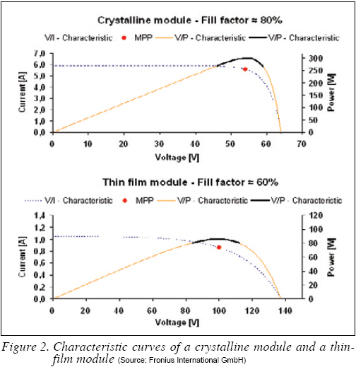
The fill factor--which is usually higher for crystalline modules than for thin film modules--is crucial, since it determines how steeply the power curve drops before and after the MPP. Figure 2 shows the typical characteristics of a crystalline module and a thin film module. It can be seen that the power curve of the crystalline module drops more steeply around the MPP than the power curve of the thin film module. Therefore, it is likely that crystalline modules lead to higher mismatching losses in east-west orientated PV systems than thin-film modules.
Another important point, however, is the change of the MPP voltage as a function of irradiation (see Figure 1). A small change of the MPP voltage over a wide irradiation range causes the fewest losses. The change in MPP voltage is mainly affected by the module temperature. A low temperature coefficient and good ventilation of the solar modules, therefore, results in better performance in east-west orientated PV systems. Moreover, a high low-light performance of a solar module can also improve the power output. Since all these variables differ with every module, no general conclusion can be drawn about which technology is more favourable for east-west orientated PV systems.
.jpg)
Results
Low Mismatching Losses
As explained previously in this article, the installation of a single inverter in an east-west orientated PV system necessarily results in mismatching losses. However, these losses are minimal and are partially compensated by other positive effects. For example, an east-west orientated PV system with a single inverter operates in a higher efficiency range for more of the time when compared to an installation with separate inverters. Figure 3, 4 use data from the east-west orientated PV system with the crystalline modules.
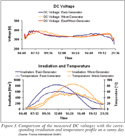
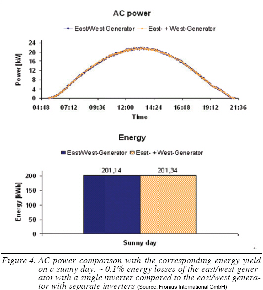
Figure 3 shows the DC voltage of the east/west generator with a single inverter compared to the DC voltages of the east/west generator with separate inverters. As can be seen, the voltages of the east and west generator are different. In the morning, the voltage of the west generator is generally higher than the voltage of the east generator, whereas the reverse is true in the afternoon. This is a result of the irradiation and temperature behaviour of solar cells, since the DC voltage remains nearly constant at a global irradiation level above ~180 W/m2 and increases/decreases with decreasing/ increasing module temperature.
The east/west generator produces mismatching losses because the DC voltage of that generator is not identical with the DC voltage of the west generator in the morning. The same applies to the DC voltage of the east generator in the afternoon. Although the DC voltage of the east/west generator deviates by up to 5% from the voltages of the generator with separate inverters, the energy losses are very small, as can be seen in Figure 4. This is because the DC voltage of the east/west generator follows the voltage of the east generator in the morning and the voltage of the west generator in the afternoon. An additional point to note is that a deviation of 5% from the optimal MPP voltage does not lead to the same percentage of power losses, since a lower/higher MPP voltage also causes a higher/lower MPP current.
As shown in Figure 4, the AC power curve of the east/west generator with a single inverter overlaps the combined AC power curve of the east/west generator with separate inverters for the whole day. The different DC voltages of the generators lead to approximately 0.5% mismatching losses but the final energy losses are just 0.1%--within the accuracy of measurement of the energy meters of ±1%. As mentioned before, the mismatching losses are partially compensated due to the east/west generator with a single inverter operating in a higher efficiency range.
The energy losses are highest on a sunny day because the lower the irradiation difference between the east and west strings, the lower the deviation of the DC voltages. The result is that energy losses are even lower on a cloudy day or on days with diffuse irradiation.
Energy Yield Comparison--Part I
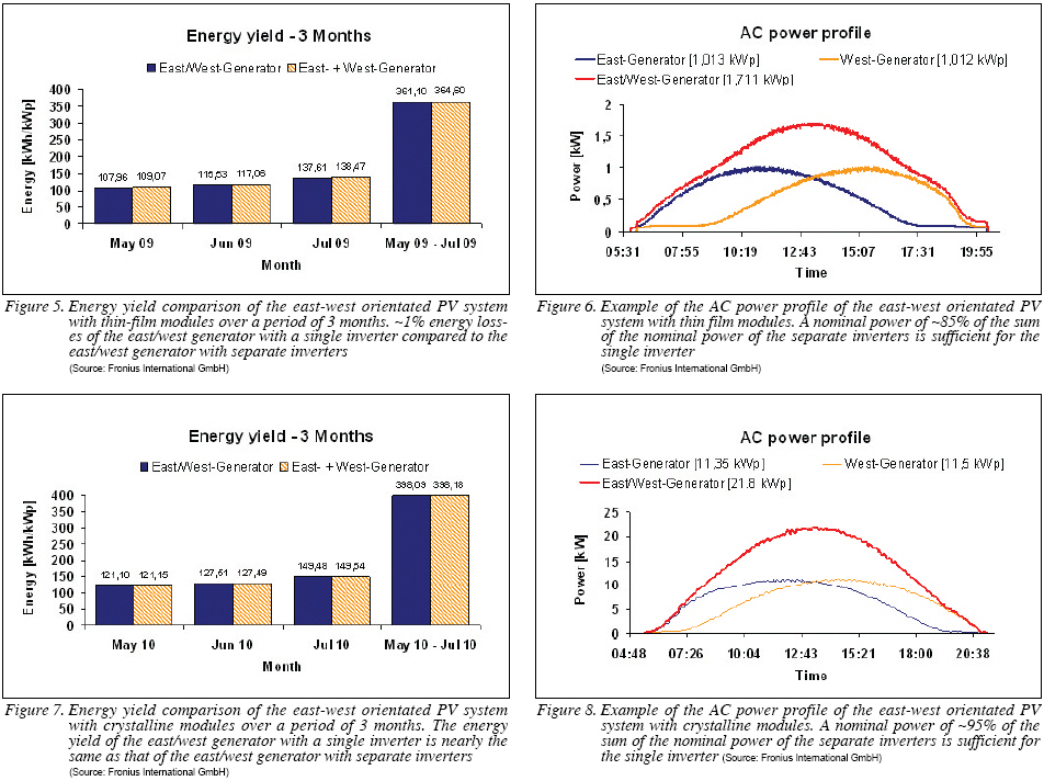
The following energy yield comparison shows the result of the east-west orientated PV system with thin film modules. As can be seen in Figure 5, the energy losses of the east/west generator with a single inverter are very low over a long period.
Based on the results from May to July, it can be expected that the annual energy losses of the east/west generator with a single inverter will be less than 1%. The east/west generator with a single inverter, therefore, has a clear advantage compared to an installation with separate inverters. It is also superior to an installation of a single inverter with two MPP Trackers. In fact, the east/west generator with a single inverter is the cheaper solution whilst generating almost the same energy yield, as only one inverter is needed. In addition, the single inverter can have a lower nominal power than the sum of the nominal power of the separate inverters. This is because the power peaks of the east and west generator are time-shifted, as shown in Figure 6. The nominal power reduction depends on the inclination angle of the solar modules--the higher the inclination angle, the lower the nominal power of the single inverter. As explained before, the thin-film modules were installed with an inclination angle of 30°, allowing the nominal power of the single inverter to be reduced by approximately 15%.
From these results it can be concluded that the cost savings are greater than the energy losses. This means that the payback time of the east-west PV system with a single inverter is shorter.
Energy Yield Comparison--Part II
The results in previous section are the energy yield comparison of the east-west orientated PV system with crystalline modules. Since the inclination angle of the solar modules is just 15°, there is very little energy loss, as can be seen in Figure 7. The mismatching losses are between 0.3% and 0.5%, but they are compensated due to the higher efficiency operation of the single inverter.
In this case as well, the east/west generator with a single inverter is the lower-cost option. The cost savings are obvious and roughly the same as set out in section PartⅠ. Firstly, only one inverter is required. Secondly, the nominal power of the single inverter can be reduced by approximately 5%, as shown in Figure 8. The nominal power reduction of 5% results from the 15° inclination angle of the crystalline solar modules. At this point, it should be mentioned that a single inverter with twice the nominal power of one separate inverter is always cheaper than two smaller inverters.
Consequently, the payback time of the east/west generator with a single inverter is shorter than that of the east/west generator with separate inverters.
Basic Installation Rules
The following rules must be observed in order to ensure that an east-west orientated PV system with a single inverter operates optimally:
-Shading must be avoided;
-The number of solar modules must be identical in all strings;
-Within a single string, the inclination angle and orientation of the solar modules must be identical.
The investigations on both PV systems have demonstrated that in an east-west orientated PV system, with a single inverter for the east and west generator, mismatching losses occur. As expected, these losses are very small and are partially compensated by the fact that the single inverter operates in a higher efficiency range. In contrast to minimal yield losses, the following costs can be reduced significantly: firstly the number of inverters can be reduced and secondly the nominal power of the single inverter can be reduced by up to 35% - depending on the inclination angle of the installed solar modules. Furthermore, installation costs can be minimized.
If one considers basic installation rules, the inclination angle of the solar modules and module technology, installing a single inverter in an east-west orientated system can be cheaper than installing a system with separate inverters. Finally, installing a single inverter has no disadvantages compared to installing an inverter with two MPP Trackers.
Dietmar Staudacher has been working for the Solar Electronics Division at Fronius International GmbH (www.fronius.com) in Austria since April 2009. After the final degree in System Engineering in 2001, Dietmar Staudacher worked as a process expert for the R&D department at Infineon Technologies.
REFERENCES
1) Fraunhofer Institute for Solar Energy Systems ISE, How fast does an MPP Tracker really need to be, 24th European Photovoltaic Solar Energy Conference, Germany, 2009
For more information, please send your e-mails to pved@infothe.com.
ⓒ2011 www.interpv.net All rights reserved.
|